Combining BIM and GIS in a Smart City Application
May 26, 2016 • Guillermo Amat

We are used to hear about Geographic Information Systems (GIS) and those of us interested in indoor applications already know the efforts of the GIS community for extending his knowledge to this new field of interest. In addition to this, architects are changing his way of work in the last years, due to the existence of new methodologies, tools and data models under the scope of the Building Information Modeling (BIM).
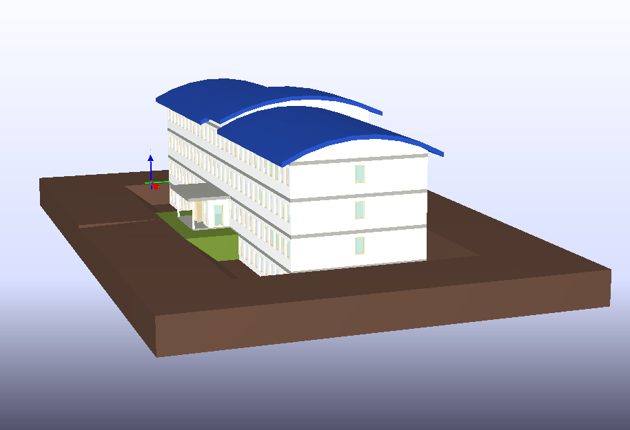
If you think about the process of creating a new indoor map, it is easy to understand that is far from perfect, especially in terms of precision when representing a building. On the other side, the BIM process includes a 3D model of the facility which is the base for its construction and so, almost giving a perfect precision. Of course, BIM models don’t include the interesting things you can find around that building such as metro stations, restaurants, etc. Why not combine these two data sources extracting the best of them? We introduced this idea at the EUBIM 2016 conference last Friday and more information is available in our paper included in the conference’s proceedings PDF (in Spanish)
To sum up, BIM has an open standard for data called IFC. The quantity of information within it is huge and contains everything needed to create a 3D model of the facility. In our case, we are interested in obtaining a 2D plan so we need to make some transformations from the original source. In addition, parsing the IFC file is a tedious task and requires a high level of knowledge of the IFC data model and its defined classes.
These days we are experimenting on creating Simple Indoor Tagging indoor maps from BIM IFC files. In other words we are transforming a .ifcxml to a .osm which can be then uploaded to Osiris. The results are quite good at this time but more work is required in order to process all the complexities of the original source. To give an idea of this, we are working with a 20 MB ifcxml file to produce a 5 KB osm file.
And now, let’s see some examples about what we are explaining.
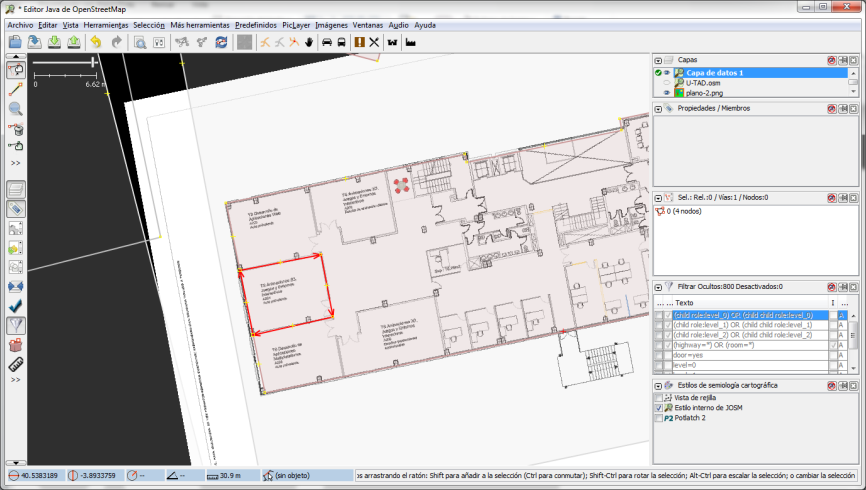
The first picture shows how we create our representation model in 2D using JOSM. The process has some imprecision because of its nature: we are overlaying the building’s floor plan to match the position of the existing venue but we cannot reach a perfect fit between both of them. Then, we draw the spaces but again, we are making errors when we trace the lines. And what about the walls? we are only drawing the approximated limits of rooms, corridors, etc. but the walls have a width which is not taken into account.

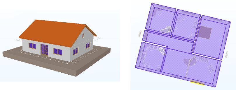
In the picture below there is a simple model of a small house shown in a BIM viewer. We have included an image of the 3D model and another one to show the 2D plan we want to have.

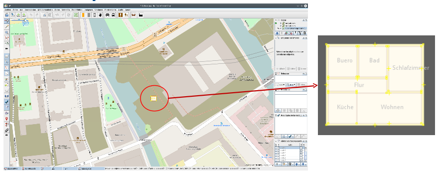
And now the results, our indoor 2D representation for this house. This model includes only the following Simple Indoor tagging entities: building, indoor, room and corridor but they have all the data corresponding to their names, levels, etc. Other important elements as the stairs, elevators and doors are not extracted yet. Moreover the ifc source is georeferenced and the construction is placed on the coordinates found in the ifc file. Lastly, there is a gap between the rooms caused by the walls.

After transforming the data we can import the resultant file to JOSM and so, the GIS data can be added. To conclude, we are going to continue with this experience and our next steps will be to extract all the missing information and to implement the building rotation to the true north.


